Hardware entrepreneurs often introduce several failed versions of beta prototypes before commercializing their product, sapping confidence from investors and spouses alike. How do you avoid multiple beta prototype modifications? Check out our “design for failure” process that can mitigate the endless cycle of product modifications.
Beta Prototypes Gone Wrong
At long last, your hardware vision has started to become a reality. You’ve done the innovative, time-intensive work to create a technically viable alpha prototype, and have finally gotten the go-ahead to develop your beta prototype. The term “beta” refers to the more polished version of your hardware product that customers can actually test out and use. In many ways, beta prototypes are built to prove that there is a real demand for the solution that you’ve created. Most startups use beta prototypes to gather customer feedback and additional data requirements to fine-tune their hardware before launch. It’s a crucial step in the design process – one that can define the overall success of the product and in many cases, the survival of the company itself.
Unfortunately, this is when many hardware startups run into trouble. Despite having created a functioning alpha prototype, they often introduce several failed versions of beta prototypes before commercializing their product. When this happens, their investors have to spend additional time and money to account for the development of the prototype changes. Not only does this cause their investors to lose confidence, but their customers may start to have doubts as well – and neither bodes well for a successful hardware launch. So, the pertinent question becomes: How do you avoid the development of multiple beta prototype modifications?
Succeed by Designing Prototypes for Failure
One of the main reasons that startups have to modify their beta prototypes is that they don’t account for potential failures during design. They don’t formally consider errors that might occur, the effects that those errors may have, or how likely or severe they could be. That’s why costly or time-intensive design modifications may be required when “unplanned” failures surface with beta prototypes.
The good news is that you can largely avoid this by designing your prototypes for failure from the beginning. To do this, we recommend that you implement Design for Failure Mode and Effects Analysis (DFMEA) as part of your beta prototype plans. At its core, DFMEA involves reviewing as many components, assemblies, and sub-systems as possible to identify the potential failure modes of your design, along with their causes and effects. For each component or process, you record the failure modes and their resulting effects on the rest of the system in a specific DFMEA worksheet. This becomes a living document through which you identify potential failures, prioritize them according to a relative risk score, and address them by executing action plans.
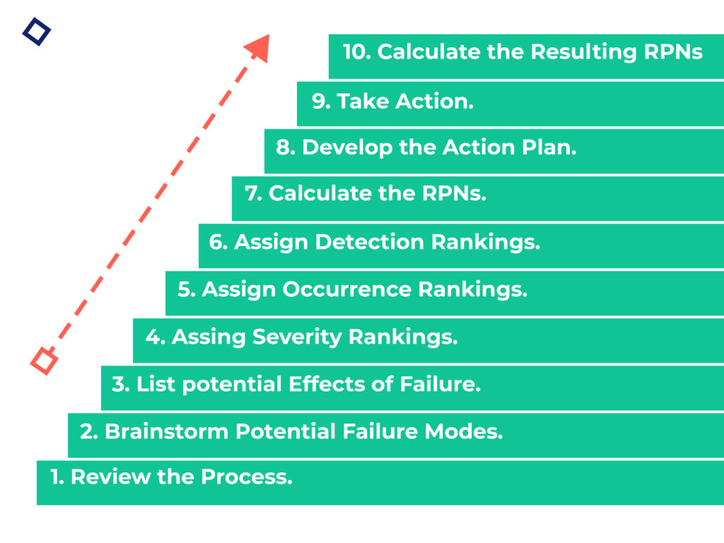
Your Ten-Step Guide to Implementing DFMEA
We’ve broken down the DFMEA approach into ten steps that you can follow to ensure that your organization is designing for failure. Keep in mind that this approach can be a complex undertaking, so make sure to allocate the necessary time and resources to implement it correctly – usually, this involves a dedicated DFMEA team to manage the process within the organization.
Step 1: Review the Design
To start, use a blueprint or schematic of your design to identify each component and interface involved with the product, along with their function(s). Not only does this ensure that all team members are familiar with the design, it serves as your foundation for the rest of the process. Add reference numbers to each component and interface to keep track as you document their functions. To take it a step further, test out a prototype or sample during your design review. Finally, engage with relevant subject matter experts to answer any outstanding questions about the design. At the end of this step, you should have a comprehensive document containing the function(s) of each component and interface. If you’re using a template like the one below, this means you’ll have completed the first column. For a more in-depth template that you can use with Excel, please refer to the FMEA Template in QI Macros.
Step 2: Brainstorm Potential Failure Modes
Before brainstorming, review any existing documentation for clues about potential failure modes. This could include customer complaints, warranty reports, or any other reports that identify things that have gone wrong (think: hold tag reports, scrap, damage, and rework). Once you have a baseline, host brainstorming sessions to consider A) what might happen to the product under difficult usage conditions, and B) how the product might fail when it interacts with other products. Consider potential “failure modes” for each component and interface, keeping in mind that many components will have more than one failure mode. Resist the temptation to leave out a potential failure mode just because it doesn’t happen often. Don’t take shortcuts here – this is the time to be thorough!
Step 3: List the Potential Effects of Failure
List the potential effects of each failure mode that you documented. An “effect of failure” is defined as the impact of a failure on a system should it occur; it’s directly related to the ability of that specific component to perform its function. Remember that failures come in different forms – some may affect customers, while others may impact the environment, product production process, or the product itself.
Step 4: Assign Severity Rankings
Next, assign a severity ranking to each failure mode. This is a critical step because it establishes the basis for determining the risk of one failure mode relative to that of another. Severity rankings are based on a relative scale ranging from 1-10. A ranking of “10” indicates a dangerously high severity, while a ranking of “1” indicates that the severity is extremely low. Check out the FMEA Severity Ranking Scale on the FMEA Resource Center as a general example.
To make the scale more customized, start with a generic version and modify it as needed. Add organization-specific examples to the ranking definitions to make it easier for DFMEA teams to apply them. This saves time and also improves the consistency of rankings from one team to another. As you outline examples, consider adding topics to provide descriptions of severity levels for different kinds of failures (i.e. customer satisfaction, environmental, health, safety, etc.). Just remember that each topic description should reflect the same relative impact in terms of severity.
Step 5: Assign Occurrence Rankings
Assign an occurrence ranking to each failure mode based on the likelihood or frequency that the cause of failure will occur. You need to know the potential cause of failure to determine the occurrence ranking. Similar to the severity ranking scale, the occurrence ranking scale is a relative scale ranging from 1-10. A ranking of “10” indicates that the failure mode occurrence is very high, or that it happens all the time. On the other hand, a ranking of “1” indicates that the possibility of occurrence is quite remote. Take a look at the general FMEA Occurrence Ranking Scale for reference.
You may need to create a customized occurrence ranking scale to apply to different levels of design. For example, it can be difficult to apply the same scale to a modular design, a complex design, and a custom design. Some organizations develop three occurrence ranking scales (i.e. time-based, event-based, and piece-based) and select the one that applies to the specific design.
Step 6: Assign Detection Rankings
Now, assign a detection ranking to each failure mode based on the chances that the failure will be detected before the customer finds it. To do this, first consider the design or product-related controls already in place for each failure mode. Then, assign a detection ranking to each control. Think of the detection ranking as an evaluation of the ability of the design controls to prevent or detect the failure. Also measured on a relative scale ranging from 1-10, a “1” indicates that a chance of detecting a failure is almost certain, while a “10” indicates that failure detection is absolutely uncertain. Refer to the FMEA Detection Ranking Scale as a starting point.
As you customize your ranking scale, consider adding examples tied to design-related topics. These could include design rules, design for assembly (DFA) or design for manufacturability (DFM) issues, and simulation and verification testing. Keep in mind that controls come in different forms and provide different levels of effectiveness. For example, prevention controls always trump detection controls.
Step 7: Calculate the Risk Priority Number (RPN)
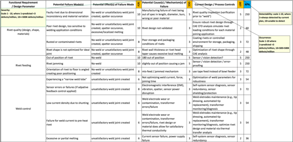
Using the prior steps as inputs, you can now calculate the Risk Priority Number (RPN). The RPN provides a relative risk ranking – the higher the RPN, the greater the potential risk. To calculate the RPN, multiply the severity, occurrence, and detection rankings together. Since each of the three rankings ranges from 1-10, the RPN will always be between 1 and 1,000. Do this for each failure mode and effect. The beauty of the RPN is that it allows you to prioritize focused improvement efforts.
As an example, consider the DFMEA worksheet below. This information was taken from a case study on automotive body structures, which involved joining dissimilar materials to make lighter-weight cars.
Step 8: Develop the Action Plan
Create action plans with the goal of reducing the associated RPN. You can achieve this by lowering severity, occurrence, and detection individually, or in combination with one another. Keep in mind that reduction in severity is often toughest as it usually requires design changes. You can reduce the occurrence ranking by removing or controlling potential causes of failure. To reduce detection, try adding or improving prevention or detection controls. You may be thinking, “What is considered to be an acceptable RPN?” The answer depends on your organization. For instance, an organization may decide that any RPN above 200 presents an unacceptable risk and must be addressed. Refer to the sample action plan below as it relates to the automotive body structure case study:
Step 9: Take Action
You can now take action on executing the action plans that you developed in the previous step. Most action plans will follow the simple “who, what, when” framework, so it should be relatively straightforward to implement the improvements. Make sure that responsibilities are clear and target completion dates for specific actions are identified. For action plans that trigger a larger-scale effort, conventional project management tools (i.e. PERT Charts, Gantt Charts, etc.) may be necessary.
Step 10: Calculate the Resulting RPN
After implementing the action plans, recalculate the resulting RPNs. This allows you to reassess each of the potential failures once improvements have been made and determine their impact on the RPNs. It helps create accountability and confirm that the action plan produced the desired results. To recalculate the RPN, reassess the severity, occurrence, and detection rankings for the failure modes.
Master Your Beta Prototype
In conclusion, you can use the DFMEA methodology to avoid failure by actually factoring it into your design process. Your investors will thank you, your customers will praise you, and you’ll avoid sinking additional time and money into multiple prototype modifications. That’s a win-win-win.
Want to learn more about how you can grow and scale your startup? Join our community of hardware entrepreneurs and get educational content delivered directly to your inbox.